Saturday, December 12, 2015

Mechanical drive train prototyping

Pace of development has definitely slowed down, as almost all of my time these days is dedicated to Mocobe, but I was feeling lazy today so we walked down to Balompie #3 and had pupusas for lunch, and then I spent some time in the afternoon tinkering with the drive train.  I've been working on it on the weekends a bit, and instead of building it all in one go, I decided that for something this complex, I was going to try roughing it out first.  This gave me a good opportunity to try a few things out and fix problems as they arose before I settled on a final design, without having to machine a lot of parts and drill a ton of holes in steel.

I used scrap aluminum plate, and did the work in my basement, with an angle grinder to cut the aluminum and a hand drill to drill the holes, which is a lot faster than drilling holes in steel with a drill press.  Fortunately, as well, I have a good sized collection of clamps, so instead of drilling into the frame, I just clamped the pieces onto it, making it easy to adjust them, remove them, and move them around.  To attach the chain to the shuttle, I made a really janky attachment point with duct tape, some wood, and a couple of eye hooks.  Eventually I'll weld an attachment point onto the shuttle, but I wanted to test this out first.


Here's the drive train in action:


Some notes from the build: 
One thing that's different from the previous version is that I added a 15 x 20 mm cable carrier to the hose.
 

It's actually two, bolted together.  The problems I was having with the hose tracking properly are totally solved by this, the hose bends fine and doesn't get tangled in the rails at all.  Since I haven't machined the sheet cladding for the whole thing yet, I hope that it will still work okay when it's constrained.

I had to make a bunch of adjustments as I was getting the drive train to work: the tensioning gear here is critical for holding the chain against the drive gear.  Otherwise the whole thing slips, there's too much play in a chain that long.  It's also really important to get these three gears aligned properly:


Otherwise, it puts a lot of strain on the swivels.  I bought swivel hubs from Servocity for mounting the sprockets (also available at Sparkfun) and found them to be junk.  The free-play of the hubs is bad, and they repeatedly fell apart when they were used under strain.  The halves are simply held together with a nylon lock nut and  a bolt.  Presumably the idea is that the lock nut prevents the bolt from loosening (or tightening!) and the halves will just rotate against the washer, without moving the bolt.  In practice, I found that in use, the hubs either fell apart or seized up due to over-tightening, depending on the direction of rotation.  It's possible that this was due to lateral strain from misalignment of the chain, which caused pressure on the washer.  In the end, I don't care why, they're not robust enough for this application.  I wound up disassembling the ones that were failing and just putting a bolt through one half, and leaving it mostly tightened.  That was fine for the time being.

I'm also thinking that a faster motor would be good.  This is running flat out, and it's got way more torque than it needs.  I'd rather get something faster, and be able to run it at slower speed using the speed controller if I need to.  I bought this one from Servocity, which runs at 118 RPM max speed, but I could just swap it out for the 313 RPM unit and I'm pretty sure the torque will be plenty.

I haven't decided on the design of the chain attachment point for the shuttle, but I'm thinking it might be handy to have some sort of short linear tensioner, like just a screw with 1" travel.  Being able to link the chain on and then screw it down to tighten would make life a lot easier.

Also, it turns out that my bicycle chain breaker doesn't work for this roller chain because the pitch is different, which isn't surprising.  I can try doing it the old fashioned way by just pounding out a rivet, but last time I tried that with a bike chain I smashed a finger.  Or I could just cut it.  I looked for a 0.25 roller chain breaker, and found this one on Amazon, but since it's made by Koch Industries,  I won't be buying it.

Sunday, November 1, 2015

Shuttle production model build notes

Hey amigos, I know it's been a while since I've rapped at ya.  I've been working on starting up a thing, which you probably already know, because if you're reading this, you're friends with me.  And if you're not friends with me, and you're reading this: welcome!  I am a handsome and accomplished man!

But, in between hacking together React widgets and swearing at JavaScript for having ever been invented, I put together a new prototype, which I am not thinking of as a prototype, it's really a test-build for a production model.  Here's the goods:

The entire thing is 8 feet long, made of two 4 foot halves.  The framed ends are 6" by 6" 0.120.  1/2" wide on the ends, and 1/4" wide on the parts in the middle.  These are held together with 1/2" square tube, welded onto the frame ends.  The rails are made of 8 foot long segments of 1/2" EMT electrical conduit.

The shuttle is similar in design to the last one, but the rail holders are solid tubes, and much larger diameter.  The 1/2" tube rails are much stiffer, and the rail holders are just welded onto the pipe holder in a single line.
The rails are held to the frame ends by 1/2" metal rod which is welded onto 1/2" wide segments of steel right angle.  These are screwed into the frame ends which are 6-32 tapped.  I broke my tap off in one of the frame ends at one point, and just used a cold chisel to break it off, and moved the hole.  It turns out that these tap extractors don't really work, at least not for a tap that small.


When the motor and chain drive are installed, I'll wrap the whole thing in 22 gauge steel (which is the thinnest I could get from Bay Metals that wasn't galvanized.)

Need to attach a hose and check how the running actually works, then buy and install a chain drive.  But, it's coming along.  The chain drive will be fun.

Sunday, October 4, 2015

Working shuttle prototype!

Simplify, simplify...after about a year of prototyping, I finally sent out some feelers and did some networking with some other fire artists, to get some feedback on my designs.  I had a good conversation with DaveX from BMOrg, who made a couple of observations that stimulated a line of thought that I had been rolling around in my head for a while.  I hacked together a prototype out of 6" diameter HVAC conduit and off-the-shelf end-caps.  All the "machining" I had to do with it was to cut a 1" slot freehand with an angle grinder, and I cut some strips from the leftover which I screwed into it to form it back into a rounder shape:

I drilled some holes in the end caps for the rails, and used the end caps from the previous prototype to hold them in place.  Then I threaded the old shuttle onto it.  With just the slot in the top, the effect is nice, but the flame is very concentrated, and it definitely has the aesthetic of something mechanically moving the flame underneath:


BUT...(and this is where DaveX's suggestion comes in), I then fit some aluminum screen over the slot, and laid some steel wool over it to use as a diffuser.  The effect is a much more organic-looking flame:


I think this looks great, and it's incredibly easy to build.  The only welding and machining is of the shuttle.  I have some issues with the hose tracking to work out, and I need to motorize it.  But this is going to be the basic design I'm going to go with for the eventual build.  I may even extend these to 8 feet long, if I'm going to start with a pyramid instead of an icosahedron, just to make it more impressive in scale.

Tomorrow morning, I'm going to start a new venture, starting up a software company.  That may or may not work.  But it is going to take up a lot of my time and my vacation is officially going to be over.  I'm very satisfied that I have a working prototype, and even if my progress slows down, I know I can get this up and running eventually.  Onward, and upward.

Friday, October 2, 2015

Shuttle prototype v5.2: Getting Better All The Time

Spent some time testing the shuttle prototype with various air intake mechanisms, some of which produced better results than others, but none fantastic.  After the intake fan burnout I decided to go with MOAR AIR.

I had two main strategies: air mixing with the gas line, and forced air into the sheath.

My initial gas mixing strategy was to inline a vacuum ejector into the gas intake, but this had no discernable effect on the output flame color or constitution, so I got rid of that quickly; if there were significant enrichment of the flame with air, I would have seen a much bluer flame, due to more efficient burning of the propane.

To test a compressed air source, I tried to build a ghetto fabulous compressor by hooking a really cheap 12V tire compressor to an old propane tank that I had converted into an accumulator:
 This worked a bit, but it took about 30 minutes to pressurize the tank to 40 PSI, and after the third time, the poor little compressor blew a gasket.  So much for plan A.

Plan B was to rent a compressor:

I hooked this up with a T into the gas line, with a check valve at the gas line to make sure the air didn't flow back into the gas line.  The compressor went up to 120 PSI, but the regulator on it wouldn't go above 60 PSI.  This turned out to be plenty though, at least for my initial tests.  Simply mixing the gas with the air, even at 20 PSI, would blow out the flame.  The regulator didn't go much below 20 PSI, so I installed a 1/4" needle valve so I could make fine adjustments to the air flow.  I wasn't able to get any improvement over the usual observations: poor flame, mostly confined to the sheath and blowing out the ends.  This was at low gas and low air flow.  At higher air flow, the flame would blow out, and at higher gas and air flow, it was about the same.

If I removed the shuttle from the sheath and ran the gas at 30 PSI, it produced a great flame.  If I slowly introduced air, I could create a nice blue flame, clearly modulating the air/fuel ratio.  By adjusting it this way, out of the sheath, I was able to ensure that I was getting the right ratio.  But putting the shuttle back in situ, the results were very similar to before, little or no sustained flame.  This suggests to me that the primary issue may not be air mixing, but ineffective ventilation of the exhaust: as soon as the gas starts burning, exhaust builds up in the chamber and snuffs the flame.  I would still expect the gas to burn under these conditions if I'm supplying enough air.  But it's possible that the "correct" ratio that I see with the shuttle in the open air is a result of the introduced air + the atmospheric air, and that in a confined space, the lack of the latter is enough to kill it.  This would suggest that it IS possible to supply enough air with the fuel, possibly.

I next tried an air manifold that inserted along the bottom of the chamber.  I took a 1/2" pipe and drilled 1/4" holes at 10" intervals, 10" from each end (so, 6 holes total).  I machined plates that fit over the fan intake fittings to hold it in place.  This also would help force the introduced air up towards the flame outlets at the top, instead of simply flowing out the open ends.


I ran these at 60 PSI, at pretty high flow rates, and fiddled with the gas to get various effects  Here's what I got at about 30 PSI gas:


The flame isn't very tight, but I'm definitely getting a translation.  At higher PSI, instead of getting a larger flame, it was simply getting spread out further, getting less localized.

I have an idea next to simply improve the ventilation of the sheath by cutting the upper half of the sides off, and seeing if this gives me the desired effect; if it does, then I can possibly reintroduce some shielding by adding sections of 6" diameter HVAC conduit.  The purpose of this is to keep the innards hidden, so that the mechanism isn't obvious.  This is the real issue I'm seeing: if I cut the top off the sheath, this would probably work, but then it would be obvious what the mechanism was, and the aesthetic would kind of be ruined.  So trying to get this to work inside the sheath, or SOME kind of sheath, seems like what I'd like to do.  Possibly going to an even larger sheath, or adding more holes to the top, or all of the above could also help with ventilation and exhaust.  Some progress, but still needs work.

Sunday, September 27, 2015

Build details on shuttle prototype v5.1

After the relative success of the shuttle prototype, I've been trying to scale this up into a design that is more similar to what I imagine the eventual final design will be like, which is to say, I've been working on building something that doesn't suck, and that I can use as a blueprint for a final design. I've stopped keeping track, but I think given the gas mixing prototype, rotational valving, translational valving, multiplexing, and shuttle prototypes, this is major version 5, making this Flaming Icosahedron v5.1.  I've done some basic experiments with it, but I wanted to take the time to write up some of my build notes here.

The sheath is made from 6"x3"x5 foot rectangular tube, 0.120 wall, which I got from Bayshore Metals.


I drilled 1/4" holes at 1/2" intervals along the top.  I managed to basically destroy my 1/4" bit along the way.  I actually took it over to the bench grinder and (after watching a YouTube video) re-ground the tip by hand, badly, but well enough to get me through the end of the drilling.  But I bought a $20 bit grinding jig for next time (and also a new 1/4" cobalt tip.)

I've posted photos of the new shuttle build before,in my last post.  I moved the rail holders to the inside to reduce the width.  The rail holders are just cut up pieces of 3/8" black pipe (which is weldable, unlike galvanized pipe.  Welding galvanized metal is a great way to inhale zinc byproducts, which will kill you slowly and painfully.)  
I also made some little clips for holding the 16ga cable in place (in v5.0, I was using picture wire twisted in place, because it's what I had lying around.  None of that bush league crap this time.)

Here you can see the shuttle in place on the rails (1/4" rod from the hardware store), with the gas supply line in place on the shuttle.

The rails are held in place on the ends with 16ga sheet metal that I bent using a handbrake and drilled and tapped holes into the sheath.  I welded 3/8" pipe to the ends, and tapped holes for set screws.
Initially, I hand measured and cut the sheet metal, but for the second set I made, for the fan intakes (below) I ran these on the water jet cutter, and it saved a lot of time.  Those needed a hole in the center for the fan intake, which would have been much harder to do by hand anyway.

Fully assembled (without the fan intakes), you can see the shuttle running along the rail very smoothly, dragging the looped-back gas line with it:

This is another one of those things where, after a week of construction, I was so happy with the results that I sat there playing with it for at least 10 minutes, just pulling the shuttle back and forth, because it worked so smoothly.  It's not a complex machine.  It's just great to imagine a thing, sketch it on the back of a donation insert at high holiday services, and then make it.

I ran a preliminary test without the intake fans, to see how it would work without any additional air, and the results were pretty predictable; at about 30 PSI, I could get okay functioning near the ends, but towards the center the flame snuffs out due to too little air:


  At 50 PSI (closer to where I'd like to run it), it doesn't really work at all.  I attached the intake fans and tried again, and the results were at first better, but there was a flame-out inside the sheath.  I see this pretty often: if not enough air gets into the middle, the fire can go out.  When propane reaches the open end, it flares up and comes out the end in a jet.  This is what you see at the beginning of this demo from v5.0.  There's no video of this run, but in this case, the flame jet came out through the intake (which was providing the air that the fire was seeking), destroying the intake fan:


So, from a build perspective, it's solid, and it works well.  I'm going to disassemble it today to check the hose, and make sure the flame-out didn't damage it.  But getting enough air in is going to require a different design.  Luckily, there are several design I'm considering: adding forced air through a compressor, adding more ventilation to the sheath, and also, carburation.  I found this design online, and reached out to the author:


I have an SMC vacuum ejector that I plan to use as my next test after I check for hose damage.  Progress!


Wednesday, September 16, 2015

Building industrial grade fire art

I was able to make the shuttle prototype functional, at least marginally, by simply slapping a fan on one end to push more air into the chamber.  Here are the results:

There's some wind, and I'm not running the gas at very high volumes, but you can see it clearly translate from one end to the other as I pull the shuttle through.  If you look at the second video closely, you'll also notice that the tygon tube has burned off the end by the time I get it back through: stress + heat = failure.  I'm very happy with this design overall, though, and am now trying to scale it up to fix the problems.  First, I came up with a new, much larger design spec, using a 3" x 6" x 5 foot sheath.  The 6" height should give me enough space to use a low-pressure braided LPG hose, which is much less flexible, and keep it well out of the way of the shuttle.  I've also redesigned the shuttle, which will run along rails

It came out a little too wide, I'm going to have to grind off the tubes which run along the rails (actually 3/8" black pipe) and move them closer to the center.  But the concept is there.

The rail will run along the top half of the 6" height, leaving the bottom half for things like hose clearance (mostly), but also having a fan on either end to push air in, some room for gearing and a motor to move the shuttle back and forth, etc.  I also started machining the ends of the sheath, which will hold the rails in place (and the fans):
These are 16 ga steel sheet which I cut and bent, then tapped holes in the sheath to hold them in place.  Fun stuff.  I screwed up the bending the first couple of times, took some practice to get it right.  But this one fits nicely.

So, this is not a "proof-of-concept" prototype.  This is intended to be an actual model for what I might eventually build to bring to the Playa, and is industrial-grade.  No joke.


Friday, September 11, 2015

Carburetion vs forced air

Some really interesting reading this morning on strategies for mixing air and gas to the right ratio.  Based on last night's experiments, this will be key to getting this to work, and I've seen gas/air mixing as critical to almost every prototype I've worked on.

Basically, you need about 96% air and 4% propane to get a good burn.  In a confined space, like the sheath tube I'm using, getting enough air in there requires an active strategy.  One strategy is to just pump air into the sheath.  This is the simplest thing, and probably what I'll try first: drill some holes in the side of the sheath, and hook up an air pump.  It's inexact, but it should work.  If I go to a pressurized air tank, I can get higher flows, and use a needle valve to tune the ratio.

But an interesting alternative is to build a carburetor that pre-mixes the propane and air.  A carburetor basically uses the Venturi effect to draw air into the stream actively before the gas reaches the outlet.  This is a good example of such a design, for a propane burner that can burn much hotter than just burning raw propane:

The writing is unfortunately pretty bad, but the gist is that the teeny hole in the middle pipe lets out propane, and it draws air in through the giant hole in the reducer.  There's not much in the way of tuning, but it works pretty well apparently, possibly just based on the specific hole sizes used.  Using a design like this in the shuttle would be complicated; it's not clear how I would adapt this.  But it's a starting point for some thinking on how to make this work.

Thursday, September 10, 2015

Quick update on the shuttle prototype

Got back from the burn and have been working on the shuttle prototype; had some good time to think about it while I was at TTITD.  Here's was the first version of the shuttle:

It used a pair of circular brackets, made from pieces from previous prototypes (I always get a bit teary-eyed when I cut up an old prototype to make a new one, but the cycle goes round-and-round.)  This was elegant, but it tended to rotate while passing through the sheath, so I had to scrap it.  The current version looks like this:


It's strapped to a couple of pieces of shelf bracket, and I've laid an aluminum rail down on the bottom of the sheath (not shown.)  I didn't film my first experiment, but the result was interesting: it worked well, once.  But it's unreliable because of poor circulation of air to the interior of the sheath.  This is an issue I've seen a lot.  I'm starting to think it might be a major issue with a number of my prototypes.  I can either pump air in (I bought a Shraeder-to1/4" NPT adapter so I can use a car tire as a compressed air source) or open up the sheath a bit.  Haven't exactly decided which.  But a quick test with just using a fan to blow air into the sheath improved it a lot.  Unfortunately the viton came out of the compression fitting after that.  Making sure the compression fitting is secure will be tricky.  In the original shuttle design above, I used a barbed hose fitting with some copper tubing soldered on to make it fit right, and ziptied it in place.  While I think this is actually more secure than the compression fitting, it's not as "legal" according to BMOrg rules.  Getting this approved will require working with them on the design, but for the prototype either is fine.

Saturday, August 29, 2015

Rotary mechanical prototype v3ish: FAILZ0R

My last rotational valving prototype showed some promise, so I decided to try a modification, with a third sheath that had a linear set of openings, so that there would be three layers:

These fit together Russian-nesting-doll style.  There's about a 1" gap between the inner and the middle, so the flame will stay alight, and the inner and outer have only about 1/16" between them, to act as the gate.  I also spent some time making a nice bracket for holding the inner pipe in place without requiring bolts, so that the outer pipe could be flush with the inner pipe.  It slides inside the middle pipe and was welded in place.  Required me to resurrect some sheet metal working skills.


The results of the test were, well, not good:

You do again see some modulation of the flame, but it's a small effect.  My impression is that the double-gating is making it such that no air is reaching the actual gas outlet at the inner tube, and we're only getting ignition as the gas escapes into the "atmosphere."  One problem with building smaller-scale prototypes and scaling them up is that you see these kinds of problems: air flow and gas flow is much worse.  I considered running an air line into the inner tube, and pumping air into it.  That said, I'm not certain that this design is a good idea overall, and I'm going to take a break from it.  The machining is fun, but it's not proving very useful.

I have some work to do on trying to improve the multiplexing prototype, but I'm less bullish on that at the moment as well given the problems.  I've been avoiding this for a while, but I think a much simpler concept might give me a much better aesthetic impression, which is basically just a small pipe that mechanically runs back and forth inside a larger pipe, like a shuttle, carrying a tube along with it, and simply carrying the flame, physically, that way:

I want to use Viton tubing to carry the gas to the shuttle, it's good to 400F, and it's resistant to propane.  But fire art safety might disagree; they seem pretty set on the idea that you can only use manufactured LP hose.  I don't think it's impossible, with a 4" diameter tube, to use manufactured hose.  It might be a future discussion if this design turns out to be good.  Having spent a lot of time working on this, I'm feeling more confident in my thoughts about safety and maybe straying outside the bounds of what is specifically published.  Including something like an excess flow check valve might help, though it might also be prohibitively expensive.

Leaving for the burn on Monday.  No more fire art for this week probably, except for running around with my backpack on.  Come find me at Playasos at 8:45 and B if you're there, and say hi.

Thursday, August 20, 2015

Experiments with flame colorants

I don't think I'll have it ready in time for the burn, but I wanted to try working with flame colorants for The Widowmaker.  Here are some experiments with solid and liquid copper sulfate. I did some experiments with boric acid as well, but those didn't turn out as well.  The key I discovered was to make a saturated solution, then use a very shallow vessle to hold it with a very small hole in the bottom; in this case, I just inverted a 1/2" end cap which had a 1/16" hole in it on top of a pipe, and held it in place with rescue tape.
The results were nice, but the gas blew most of it out.  Spraying it directly into the flame might be workable, but the timing would have to be just right, and I wonder if I can get enough volume.  I don't have a spray bottle sitting around that I want to ruin with copper sulfate just now, so it will wait a bit until I get one from The Jerk Store.

Wednesday, August 19, 2015

Multiplexing scale prototype

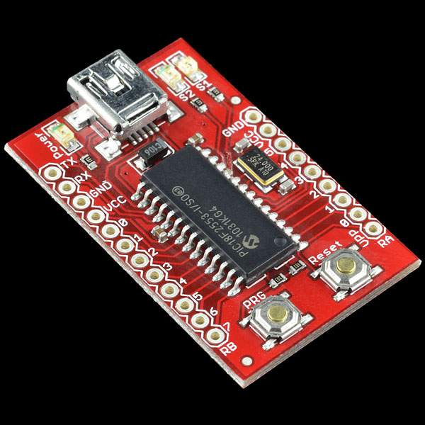
Built a larger scale prototype of the multiplexing concept.  For control, I tried something new, using the USB Bit Whacker:
Instead of using a microcontroller, you can bit twiddle this in Java (or in Groovy, in my case) using simple serial port commands.    I used JSSC for the serial port communication because javax.comm is way too complicated, and as far as I can tell is not part of the JDK or hosted on Maven Central.  (If it's not on Maven Central, I don't need it.)  The main reason for trying the Bit Whacker was that, when using the Arduino, the compile-upload-run cycle is long, and getting feedback (button presses, whatever) into the system is non-trivial.  The Bit Whacker lets me iterate on variables and protocols much more quickly.  Also, I can do things like start it up, open a valve, put it in an idle state waiting for keyboard input while I light the flame, and then hit a button to continue the program.  I can do this really easily, whereas with the Arduino it requires actually attaching a button and reading input from it.

I placed 6" lengths of 1/16 inch holes at six inch spacings, with 3 strands with 3" overlaps.  I re-used the valve array plumbing from the electromechanical prototype.  Here are some test videos at two different flow rates:


The lighting makes it hard to see what's going on, but there are two main problems:  First, because there are holes all along the length, the gas pressure at the distal end is much lower than at the proximal end.  This is especially apparent in the first video.  This is easily fixable by creating a loop of the tube and plugging both ends into a t-junction, but it's more plumbing, and a pain in the ass.

Second, in the second video, you can see that the first segment ignites, then the second segment, in sequence, and the first goes out (mostly.)  Then the second ignites the third.  At this point, the first segment comes on again, and should ignite the next length of the first segment.  The problem is that the original position flares back up, and we get two flame fronts.  Why?  Because the flame never actually goes out; when I shut down the gas flow to the first segment, there's still residual propane in the pipe, and it doesn't burn off or go out immediately.  It just goes to a very low flame.  This can persist for minutes at a time.  If I want to continue with this prototype, I'll need to figure out a way to deal with this.  It's not a failure, but there are bugs to be worked out.  Every bug fix introduces new complexity, and the goal is to make the design as simple as possible, but no simpler.

Also notable about this run was that it was the first time I had to use my fire extinguisher.  The solenoid valves are poor quality (I guess that's what you get from $9 a valve on Alibaba) and there was some leakage from one of the unused valves that's supposed to remain closed when unenergized.  I was trying to work around it so I could do a quick and dirty test, but it caught fire, and wouldn't go out because of the volume of gas leaking.  I decided to extinguish it for safety, since it was close to a few things that I didn't want to catch on fire.  Safety third!  (A friend of mine told me once that they saw a t-shirt that said:

1) Porn
2) Bacon
3) Safety

But I can't find it on the intarwebz.  Would be fun to have.  Suppose I could make one.)

Sunday, August 16, 2015

Successful test of the fire poofer backpack

Bad video quality, but it worked.  I'm probably going to replace the PVC with copper, since the top did stay on fire a bit after the initial poof, and it did char the top of the PVC.  But otherwise, total success.

I'm thinking this thing needs a name, I'm thinking of just calling it The Widowmaker.  But I'm open to suggestions.

Friday, August 14, 2015

Making a Thing (with Metal)

I quit my job a couple of weeks ago.  I was bored, and I wanted to do something else.  And I'm kind of looking around.  But in the meantime, I'm working on fire art more, prepping for the burn, and going fishing.  Today, I Made a Thing™.

When I was young, and I wanted to make something, I was always baffled by how you went from an idea to a thing.  In my mind, I guess, I didn't really think there was anything you could do between woodworking and drop forged steel; if you wanted a thing, and it wasn't made of wood, you were pretty much out of luck unless you wanted 10,000 of them.  I don't think I thought it explicitly, but I think it was pretty much how I figured the world was.  Only professionals could Make a Thing™.

Doing a bachelors and a doctorate in physics, you're highly encouraged to take machine shop.  There are a lot of simple situations where you have a sensor, and something you want to attach it to, for instance, and they don't fit.  So you machine an adapter plate.  I was instantly in love with machining, and would often find excuses to go to the machine shop to make things*, especially in grad school.

Since then, a lot of things have changed that made it easier to Make a Thing.  For one thing, Make magazine, Instructables, and the entire maker/DIY movement have made it much easier to learn how to make things, especially if you came from a family that did not make things (my father is a lawyer, and is a great lawyer, but was never much with hand tools.  We did build a passable treehouse together, though.  That was a great memory.)

For another, there are a lot of ways to make things that didn't exist back then.  There are low temperature moldable plastics, 3D printing (even in metal!), and all kinds of CNC that never existed.  The flowjet at TechShop is one of my favorites, especially for making signs:


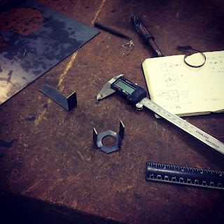
But for me, personally, having a house, and having tools, and knowing how to use them was really the biggest step, in some sense.  It's just wonderful to me that I can Make a Thing, in my own house, in a few minutes, and even simple things give me great pleasure.  As part of my backpack flame poofer (almost completed), I made a bomb-style thumb button, and wanted to have a clip to clip it to the backpack strap.  So I grabbed a piece of 16 gauge steel, bent it around the handle, cut off the end with a dremel, shaped it a bit, and drilled a couple of holes in the back to mount it:


\
The way it snaps into the holder gives me great pleasure.  I Made a Thing, and it does its job very well.

*This was way back in the very earliest days of Make magazine, and I was super excited that there was a web site just for showing off stupid stuff that you made.  Unfortunately, the original site is now lost down the memory hole, but it's not hard to imagine what we did.

Wednesday, August 5, 2015

Notes on tasering oneself

Been working a bit on the backpack poofer in the lead up to the burn, the electronics of which have been surprisingly hairy.  Turns out, dealing with two high power loads (electric ignitor and valve both take 3A) at different voltages (5V and 12V respectively) is a bit trickier than I thought.  A few interesting notes:


  • Was getting frustrating hard-to-reproduce failures of the microcontroller after actuating the spark gap ignitor.  Turns out that sucker puts out a LOT of electromagnetic interference.  It was mounted near the Arduino.  At the advice of a friend, I moved the ignitor up to the top of the gas exhaust, and ran the 5V line up to it, instead of running the high voltage from the backpack all the way to the top.  This got rid of the problems, by creating a much shorter line, and separating the ignitor, which was probably putting out a lot of juice.  Working with digital electronics gives you the false impression of modularity.  Analog high power electronics puncture that balloon quickly.
  • The ignitor is very high voltage at up to 3A.  Because the microcontroller was acting up intermittently, I thought it was off when I unplugged the ignitor and had both of the (insulated) ends of the plugs in my hands when it suddenly actuated.  I thereby became the spark gap.  I was dropped to the floor cursing and screaming bloody murder, but there was no permanent damage.  Fun with electricity!

Tuesday, August 4, 2015

Multiplexing prototype

Had a new idea when I was on a run yesterday.  It's nice to be at a point where I can test out this stuff without much expenditure because I've already acquired so much scrap and spare parts that I can throw it together quickly.  Here's a way to possibly multiplex two or three valves to get higher resolution travel:

These are two lengths of 1/8" copper tube with 4" lengths of 1/16" holes at 1/4" spacing.  They're fed from the same line, there's no valve, but it's set up in such a way that I can adjust the spacing in between them.  With a 4" separation between the two, we get immediate ignition of both:

But with a 5.5" separation, the second set remains unignited, even after the first is ignited:


What this means is that, with only three valves, I can cause the flame to travel by leaving gaps and sequentially turning them on, and still get 3" resolution by actuating them in sequence, repeatedly:


Of course, one problem is that the ignition distance and speed is going to depend a lot on the airflow around the unit.  If we try to hide the mechanics here by putting it inside a 1/2" pipe with 1/16" holes at 1/2" spacings (which I just pulled out of the last rotary prototype and slid over it):
The effect is quite nice, however, of the bar "catching fire" as the flame travels, almost what I want, but in this case the flame doesn't "turn off" behind the front, giving us just a single moving front, not a flame "quantum".  However, it makes it clear that encasing this to protect it from the wind will be tricky.  If I can get a three-fold multiplexed design to work in the lab, I'd like to try encasing it in a 2" or 3" tube, where I cut large spacings out of the sides of the tube, and possibly line it with a fine metal mesh.  If we want to be cool about it, we can cut different shapes into the sides, possibly using the flow jet.  This will maybe let the gas diffuse away, so we don't get instant ignition, but give it some wind protection, and give the effect of the flame being "encased".


Wednesday, July 29, 2015

Notes on telescoping tubing

This is actually really, really handy.  And looks like a cheaper source for prototyping sizes (e.g. 48" of tubing) than buying direct from local sources (where I have to buy 20' or not at all.)

Electromechanical valving prototype

Simplest possible thing you can imagine: five solenoid valves, each feeding a separate pipe, actuated in sequence.
The effect was about what I expected: not very smooth.  If I put another five of these in a row, it might look better, but in general this is what I'm going to get.  If I want to do this for real, two things to improve:

1) I want to make these all highly linear, in a single tube format.  That might mean devising a way to create end-to-end pipes or tubes, with internal threading and seals between them, and then using copper tube to run out of each unit.  Or, encasing the whole thing in a larger tube.

2) Diffusing the flame a bit to improve the visual effect.  I can't fit the "rail" I made over this unit (the pipes are a bit skewed because, with the caps, they don't fit properly in a single line.  But putting the whole thing in a larger tube might do it.

I'm not thrilled with the effect, but not sure how to improve it other than using MOAR SOLENOIDS.  And the amount of labor to get just one of these working right is quite large.  I still haven't figured out a way to multiplex with fewer valves.

Another rotating mechanical valve prototype kind of sucked, but I have an idea for improving it:

This is a 1/2" pipe inside a much larger diameter pipe.  The larger diameter pipe has slots cut at different offset angles. The difference between this design and previous similar designs is the gap between the inner and outer is intentionally large so the flame is always lit.  The outer simply "gates" it.  Two issues came up here:

1) This video makes it look like it works better than it does.  The wind is a huge factor.  I saw this on the playa last year as well with my smaller flame art.
2) The gating doesn't work that well, I saw similar "leakage" to what I saw with previous rotating prototypes.  My thought here is to add yet a third layer, on the outside, which has a series of holes along the top.  This increases the complexity a lot, again, but I do like the way this one gives a smooth translation effect.  I think it's worth trying.  

My original estimation was that electromechanical valving would be more expensive but easier; it turns out that doing it right isn't really easy.  The amount of plumbing required is significant (see above.)  So it's not clear that, even with a three pipe design, that this is much more complicated.  Especially if no precision machining is required, which it isn't.  Work-holding on a 4-foot pipe is a problem that I found (I created the slots with a 3/8" end mill, and the pipe would slip sometimes.)  But not insurmountable.

Thursday, June 25, 2015

Some lessons about pipe dope

Mostly a lab note to myself: I've been having a lot of gas leaks, and have been experimenting with ways to ensure that they don't recur.  Ideally I should seal something once, and it's sealed, and not have to test, re-test, etc.  So I've tried using pipe dope instead of teflon, and have had somewhat improved results.  But ordering matters; the solenoid valves from Alibaba leak around the joints if you don't do it right, probably because they're cheap.  So, first I apply dope to the nipple going into the inlet, then I apply dope to the female threads of the valve.  I thread the nipple and tighten it down with a vice grip, then I can hand tighten the valve into the rest of the assembly.  Above the valve everything will be at atmospheric pressure (because that's where the gas comes out) so the seals are less important.

A problem I've had for a long time is ensuring that multiple pipes line up appropriately, and I still don't have a great answer for this.  Roughly speaking, imagine you have two pipe tees connected by a pipe.  I'd like to have them both facing the same way, but that means that they need to screw in tight into exactly the same position, and they often don't.  Sometimes hand-tight is at 90 or 180 degrees; in this case, wrenching it down to the same position either takes a lot of force, or leaves them slightly loose.


The answer here and here seem to suggest that a lot of pipe dope and/or teflon should help, plus there should be at least +/- 1 turn slack on a joint that's tight enough.  For water I'm sure it's good.  For 30 PSI gas, not sure. 

Wednesday, June 24, 2015

Disappointing results, new learnings

Not a great week for the prototypes.  Things did not work out as hoped, but things were also learned, some of which were obvious in hindsight.  But even obvious things, it's good to experiment with, because sometimes the things that seem obvious are wrong.

Low-fi linear valving
I had some success with the linear valve prototoype based on square stock, and wanted to try a similar idea with some modifications: I wanted to try it with round stock (one of which was a pipe), to reduce costs and machining complexity.  And I spaced the holes much further, an inch apart, and did all the work with a drill press instead of machining.  I wanted to see if I could make a "low-fi" version of this that would be cheaper and easier to make.  I reasoned that placing the holes further apart would help reduce hole-to-hole gas leakage, and also make the absolute registration of the holes between the parts less important, so that simple drilling with approximate hole locations would be okay.  I used 1/16" holes.  I also broke a couple drill bits doing this before I remembered that, with drilling, slower is not always better: with such a small bit, a very high RPM is much better, because otherwise I get impatient and put too much stress on the bit.

I also experimented with sealing the ends with epoxy (JB Cold Weld) instead of soldering or welding, which actually worked pretty well.  For a prototype, at least, it's a lot simpler and quicker, and there were no heat issues because the seals were far from the flames.  So, yay for quick and dirty.

Unfortunately, total fail:

There's basically full leakage, no valving at all, not even significant modulation of the flame height on actuation.  So, what did we learn?

First, hole spacing isn't really changing the leakage.  This should be obvious if the pressure is at or close to equilibrium, and this says that it basically is.  Again, should be obvious, but experiment confirms it.  Second, this behaves a lot like the rotary prototype: total leakage.  That suggests that the main problem is the pipe/cylinder shape.  The part tolerance is lower (based on what I was able to source), but also, the pipes make contact at a single point:
The size difference is exaggerated here, but the principle is the same: circles only touch at one point, meaning that there's just not much overlap to gate the flow with.

For a mechanical valving prototype that means that basically we must go with square stock.  That's certainly possible, but it will be necessary to figure out the relative cost.  I might have to contact some suppliers on Alibaba to figure out if this is worthwhile.  I may also use my remaining square stock to see if I can do the low-fi machining thing, and find a better way to seal them, which was the previous problem.

I have one other theory about a potential rotary mechanical valving prototype, whis is to actually leave a large gap, of half an inch say, and actually let the inner tube be fully on fire.  The outer tube will them simply gate the flame from coming out and being visible.  This may not work: the flame may simply want to travel too much; after all, the flame is really just hot gas.  It will also make the outer tube VERY hot, but it won't be on for long in the eventual art work, so maybe not that hot.  Anyway, something I can try quickly and easily I think.

Solenoid valves
I tried a simplified attempt at building a solenoid valve prototype with four valves and three inch separators.  Instead of building a full rail on top, I took a U-channel and drilled holes, and placed them atop the open pipes.  I was hoping to use this to diffuse the flame somewhat, and reduce the complexity.


The result here was just a lot of gas leakage, and eventually a huge fireball.  Not a big failure, just wanted to see if I could do this on the cheap.  I'll buy some more pipes and see if I can make a full rail on top, with holes drilled etc.

Also, these things draw like 3 amps each.  I was thinking of doing some pulse width modulation, but this might be complicated.  I'm going to see if I can maybe run these from an Arduino with a big ass MOSFET and a snubber diode.  But even if I don't blow up my Arduino (which I might), I may not be able to effectively pulse width modulate them.  We'll see.

Edit: On second thought, this motor driver with a snubber diode looks better designed for the purpose: https://www.sparkfun.com/datasheets/Components/General/L298N.pdf

Tuesday, May 19, 2015

Propane rifle

This is a nice effect:
http://technabob.com/blog/2015/05/18/diy-propane-rifle/


Wrapping the tubing gives the flame front the appearance of a longer transit time.  You could imagine doing a helical wrap around a clear tube and getting a nice mostly-linear effect.  And using the propane torch as the mixing element is also nice, because it's designed to mix air-propane at the inlet.  No calculations needed!  Might even be able to modulate it by modding the inlet a bit...

Friday, May 8, 2015

Money, money, money...

I bought some round telescoping tubing from McMaster-Carr, hoping that it would give me tight tolerance fittings, but it doesn't.  The tolerances are crappy, like 1/8" difference in ID and OD.  I'm hoping to retry the linear model with 4 ft long tubing, and also possibly a new rotational valving model with the following changes:

  • Tighter tolerance tubing
  • Have the outer tube holes all facing upwards, and the inner tube with the helical holes
  • Use 1/16" holes instead of the 1/8" holes I used in the original prototype
I'm just going with my gut on these changes, that they might improve the performance and appearance of the effect.  The problem with swapping the helical holes into the inner tube is that it requires the inner tube to rotate, and the inner tube is connected to the gas supply.  Rotating it by 90 or 180 degrees should be possible as long as the hose is long enough.  I looked at gas swivel joints, but they're really expensive.

On the other hand, I found a really cheap source of solenoid valves on Alibaba, like less than $10 a valve.  The shipping is expensive (from China) but if I decide to go with these in bulk, it's pretty tractable.  I think testing a system with about 10 valves along a 4 foot line might be actually quite doable from a cost and complexity standpoint.  I was thinking this would be prohibitive, but really, I think $3000 in valves isn't actually that much in the grand scheme of things.   I had also originally thought this would require me to to build several independent lengths with holes and their own inputs but I want to try simply attaching them under a square U-Channel with holes drilled at intervals.  It would depixelate the effect but still be pretty simple to build.  The control logic becomes much more complicated, but control logic is in some sense the easy part: one controller per edge, and a central controller.  Not that big a deal.

Monday, May 4, 2015

Linear mechanical valve prototype: qualified success!

!!! Big Red Warning Header !!!

I have zero training in flame art apart from what I've been reading on the internet, and having a doctorate in physics.  Don't attempt any of this.  Don't blame me if you get hurt.  Don't build dangerous things in your basement.  It's a bad life choice for 99.9% of the population.


So, this is based on the same mechanical valve principle, but instead of the rotary motion, it uses a linear motion, with distances between the inner and outer holes progressively offset, so that moving the outer shield uncovers different sets of holes.  I set it up with two holes per offset, and half-hole offsets per stop, so that there's always a progression: as one set of two holes is fully opened, the adjacent holes are half-opened.  This helps give the flame a more continuous effect, and ensures that it gets translated as the new holes valve open.

Some observations:
  • I bought hollow square stock from McMaster-Carr, and specifically found stock with very tight tolerances, to prevent leakage from one hole to the next.  I also used a layer of high temperature automotive grease between them, both for the lubrication and to help prevent gas seepage.
  • Working with square stock is hard.  I am a very bad welder, and I tried to weld the ends shut (one end I welded a cap, so that I could disassemble it if needed.)  It's not easy to weld a gas-tight seal, and I wound up using silicone sealant and rescue tape (which I spotted at my local hardware store when buying the silicone sealant), and the seal still wasn't fantastic.  Silver solder would have given me a better seal, but on parts this big I worried that it would take a shitload of propane to get them to the right temperature.  And, I can't use silver solder in production, because of the melting risk (FAST prohibits it, and unlike my other, ahem, projects, I care about getting this one approved.)
  • Also, I should be working with brass.  I didn't really check if there was brass stock available with the right dimensions, but there are fewer options in general, so I might not have been able to.  On the other hand, it's so much easier to work.  I broke a few drill bits trying to drill screw holes into the ends of this thing (don't ask), and gave up and welded the ends on instead.
  • While this looks like a good option, it's going to be very hard to scale up.  Precision machining on a 12" scale is time consuming.  I literally have no idea how I would do this with a 4 foot part, the mill won't accommodate it.  And then multiply that by 30 edges.  I'd like to see if I can get a similar effect with pipe stock, which is cheaper.  Also possibly make the holes much further apart; in that case, each valve would have to have its own pilot (via a continuous copper line, probably), but the machining wouldn't need to be precision, you could simply measure and drill.  The trick again I think is getting parts with tight enough tolerance.  But if the holes are spaced far enough, that may not even be an issue.  Will have to experiment more...