Thursday, June 25, 2015

Some lessons about pipe dope

Mostly a lab note to myself: I've been having a lot of gas leaks, and have been experimenting with ways to ensure that they don't recur.  Ideally I should seal something once, and it's sealed, and not have to test, re-test, etc.  So I've tried using pipe dope instead of teflon, and have had somewhat improved results.  But ordering matters; the solenoid valves from Alibaba leak around the joints if you don't do it right, probably because they're cheap.  So, first I apply dope to the nipple going into the inlet, then I apply dope to the female threads of the valve.  I thread the nipple and tighten it down with a vice grip, then I can hand tighten the valve into the rest of the assembly.  Above the valve everything will be at atmospheric pressure (because that's where the gas comes out) so the seals are less important.

A problem I've had for a long time is ensuring that multiple pipes line up appropriately, and I still don't have a great answer for this.  Roughly speaking, imagine you have two pipe tees connected by a pipe.  I'd like to have them both facing the same way, but that means that they need to screw in tight into exactly the same position, and they often don't.  Sometimes hand-tight is at 90 or 180 degrees; in this case, wrenching it down to the same position either takes a lot of force, or leaves them slightly loose.


The answer here and here seem to suggest that a lot of pipe dope and/or teflon should help, plus there should be at least +/- 1 turn slack on a joint that's tight enough.  For water I'm sure it's good.  For 30 PSI gas, not sure. 

Wednesday, June 24, 2015

Disappointing results, new learnings

Not a great week for the prototypes.  Things did not work out as hoped, but things were also learned, some of which were obvious in hindsight.  But even obvious things, it's good to experiment with, because sometimes the things that seem obvious are wrong.

Low-fi linear valving
I had some success with the linear valve prototoype based on square stock, and wanted to try a similar idea with some modifications: I wanted to try it with round stock (one of which was a pipe), to reduce costs and machining complexity.  And I spaced the holes much further, an inch apart, and did all the work with a drill press instead of machining.  I wanted to see if I could make a "low-fi" version of this that would be cheaper and easier to make.  I reasoned that placing the holes further apart would help reduce hole-to-hole gas leakage, and also make the absolute registration of the holes between the parts less important, so that simple drilling with approximate hole locations would be okay.  I used 1/16" holes.  I also broke a couple drill bits doing this before I remembered that, with drilling, slower is not always better: with such a small bit, a very high RPM is much better, because otherwise I get impatient and put too much stress on the bit.

I also experimented with sealing the ends with epoxy (JB Cold Weld) instead of soldering or welding, which actually worked pretty well.  For a prototype, at least, it's a lot simpler and quicker, and there were no heat issues because the seals were far from the flames.  So, yay for quick and dirty.

Unfortunately, total fail:

There's basically full leakage, no valving at all, not even significant modulation of the flame height on actuation.  So, what did we learn?

First, hole spacing isn't really changing the leakage.  This should be obvious if the pressure is at or close to equilibrium, and this says that it basically is.  Again, should be obvious, but experiment confirms it.  Second, this behaves a lot like the rotary prototype: total leakage.  That suggests that the main problem is the pipe/cylinder shape.  The part tolerance is lower (based on what I was able to source), but also, the pipes make contact at a single point:
The size difference is exaggerated here, but the principle is the same: circles only touch at one point, meaning that there's just not much overlap to gate the flow with.

For a mechanical valving prototype that means that basically we must go with square stock.  That's certainly possible, but it will be necessary to figure out the relative cost.  I might have to contact some suppliers on Alibaba to figure out if this is worthwhile.  I may also use my remaining square stock to see if I can do the low-fi machining thing, and find a better way to seal them, which was the previous problem.

I have one other theory about a potential rotary mechanical valving prototype, whis is to actually leave a large gap, of half an inch say, and actually let the inner tube be fully on fire.  The outer tube will them simply gate the flame from coming out and being visible.  This may not work: the flame may simply want to travel too much; after all, the flame is really just hot gas.  It will also make the outer tube VERY hot, but it won't be on for long in the eventual art work, so maybe not that hot.  Anyway, something I can try quickly and easily I think.

Solenoid valves
I tried a simplified attempt at building a solenoid valve prototype with four valves and three inch separators.  Instead of building a full rail on top, I took a U-channel and drilled holes, and placed them atop the open pipes.  I was hoping to use this to diffuse the flame somewhat, and reduce the complexity.


The result here was just a lot of gas leakage, and eventually a huge fireball.  Not a big failure, just wanted to see if I could do this on the cheap.  I'll buy some more pipes and see if I can make a full rail on top, with holes drilled etc.

Also, these things draw like 3 amps each.  I was thinking of doing some pulse width modulation, but this might be complicated.  I'm going to see if I can maybe run these from an Arduino with a big ass MOSFET and a snubber diode.  But even if I don't blow up my Arduino (which I might), I may not be able to effectively pulse width modulate them.  We'll see.

Edit: On second thought, this motor driver with a snubber diode looks better designed for the purpose: https://www.sparkfun.com/datasheets/Components/General/L298N.pdf

Tuesday, May 19, 2015

Propane rifle

This is a nice effect:
http://technabob.com/blog/2015/05/18/diy-propane-rifle/


Wrapping the tubing gives the flame front the appearance of a longer transit time.  You could imagine doing a helical wrap around a clear tube and getting a nice mostly-linear effect.  And using the propane torch as the mixing element is also nice, because it's designed to mix air-propane at the inlet.  No calculations needed!  Might even be able to modulate it by modding the inlet a bit...

Friday, May 8, 2015

Money, money, money...

I bought some round telescoping tubing from McMaster-Carr, hoping that it would give me tight tolerance fittings, but it doesn't.  The tolerances are crappy, like 1/8" difference in ID and OD.  I'm hoping to retry the linear model with 4 ft long tubing, and also possibly a new rotational valving model with the following changes:

  • Tighter tolerance tubing
  • Have the outer tube holes all facing upwards, and the inner tube with the helical holes
  • Use 1/16" holes instead of the 1/8" holes I used in the original prototype
I'm just going with my gut on these changes, that they might improve the performance and appearance of the effect.  The problem with swapping the helical holes into the inner tube is that it requires the inner tube to rotate, and the inner tube is connected to the gas supply.  Rotating it by 90 or 180 degrees should be possible as long as the hose is long enough.  I looked at gas swivel joints, but they're really expensive.

On the other hand, I found a really cheap source of solenoid valves on Alibaba, like less than $10 a valve.  The shipping is expensive (from China) but if I decide to go with these in bulk, it's pretty tractable.  I think testing a system with about 10 valves along a 4 foot line might be actually quite doable from a cost and complexity standpoint.  I was thinking this would be prohibitive, but really, I think $3000 in valves isn't actually that much in the grand scheme of things.   I had also originally thought this would require me to to build several independent lengths with holes and their own inputs but I want to try simply attaching them under a square U-Channel with holes drilled at intervals.  It would depixelate the effect but still be pretty simple to build.  The control logic becomes much more complicated, but control logic is in some sense the easy part: one controller per edge, and a central controller.  Not that big a deal.

Monday, May 4, 2015

Linear mechanical valve prototype: qualified success!

!!! Big Red Warning Header !!!

I have zero training in flame art apart from what I've been reading on the internet, and having a doctorate in physics.  Don't attempt any of this.  Don't blame me if you get hurt.  Don't build dangerous things in your basement.  It's a bad life choice for 99.9% of the population.


So, this is based on the same mechanical valve principle, but instead of the rotary motion, it uses a linear motion, with distances between the inner and outer holes progressively offset, so that moving the outer shield uncovers different sets of holes.  I set it up with two holes per offset, and half-hole offsets per stop, so that there's always a progression: as one set of two holes is fully opened, the adjacent holes are half-opened.  This helps give the flame a more continuous effect, and ensures that it gets translated as the new holes valve open.

Some observations:
  • I bought hollow square stock from McMaster-Carr, and specifically found stock with very tight tolerances, to prevent leakage from one hole to the next.  I also used a layer of high temperature automotive grease between them, both for the lubrication and to help prevent gas seepage.
  • Working with square stock is hard.  I am a very bad welder, and I tried to weld the ends shut (one end I welded a cap, so that I could disassemble it if needed.)  It's not easy to weld a gas-tight seal, and I wound up using silicone sealant and rescue tape (which I spotted at my local hardware store when buying the silicone sealant), and the seal still wasn't fantastic.  Silver solder would have given me a better seal, but on parts this big I worried that it would take a shitload of propane to get them to the right temperature.  And, I can't use silver solder in production, because of the melting risk (FAST prohibits it, and unlike my other, ahem, projects, I care about getting this one approved.)
  • Also, I should be working with brass.  I didn't really check if there was brass stock available with the right dimensions, but there are fewer options in general, so I might not have been able to.  On the other hand, it's so much easier to work.  I broke a few drill bits trying to drill screw holes into the ends of this thing (don't ask), and gave up and welded the ends on instead.
  • While this looks like a good option, it's going to be very hard to scale up.  Precision machining on a 12" scale is time consuming.  I literally have no idea how I would do this with a 4 foot part, the mill won't accommodate it.  And then multiply that by 30 edges.  I'd like to see if I can get a similar effect with pipe stock, which is cheaper.  Also possibly make the holes much further apart; in that case, each valve would have to have its own pilot (via a continuous copper line, probably), but the machining wouldn't need to be precision, you could simply measure and drill.  The trick again I think is getting parts with tight enough tolerance.  But if the holes are spaced far enough, that may not even be an issue.  Will have to experiment more...

Thursday, April 30, 2015

In other news...

Haven't had much time to work at the machine shop since my shoulder surgery and international travel for work, but have been slowly making progress on a new prototype.  This, however, is something I made at home without any machining:


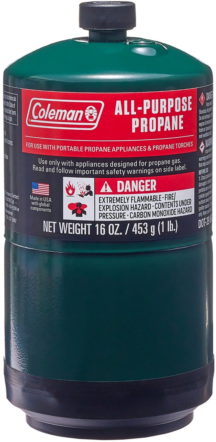
It's a flame poofer of the usual type that you see at the burn, pretty easy to build, with a solenoid controlled valve.  But the difference is that I built this one with camping stove propane containers, the small 16 oz ones:
With a bit more plumbing, this could easily fit inside a backpack.  This would almost certainly be a violation of the fire art safety rules, though, a portable backpack-worn poofer...so I definitely will NOT be running around deep playa with one of those.

I've also considered the thought of passing that flame through an acrylic tube, of the sort I was using for the slow-burn prototype, just to see what the effect was.  I may still give that a shot.

Saturday, January 24, 2015

Mechanical valving prototype, v1

!!! Big Red Warning Header !!!

I have zero training in flame art apart from what I've been reading on the internet, and having a doctorate in physics.  Don't attempt any of this.  Don't blame me if you get hurt.  Don't build dangerous things in your basement.  It's a bad life choice for 99.9% of the population.

A camp mate of mine suggested a design for a mechanical valving mechanism with an inner and outer pipe.  The inner pipe would have a line of holes to allow gas to escape, and the outer pipe would have holes at the same spacings, but in a spiral, so that as the pipe was rotated different sets of holes would come into register.  He did a 3D rendering, showing two options (spiral holes on the inner and outer pipes):


During some meetings a couple of weeks ago during which my attention was possibly less engaged than it could have been, I drew up some rough mechanical drawings, including valves, servo motor, pilot, and how to joint them at the ends:


Last weekend I had most of the weekend free, and spent some time working on the prototype.  I used a 30" length of 1/2" galvanized pipe for the inner pipe, and chose to make the outer pipe the rotating one, so that I wouldn't need a swivel valve.  I took my pipe over to Bay Steel, which I highly recommend on account of the fact that they're open on Saturdays, they're cheaper than Bayshore Metals (which is not open weekends), and they let me use their cutoff wheel for free to cut the 20' lengths down so I could put them on my truck rack.  (I tried to be pretty careful with the cutoff wheel, but the old Chinese dudes who worked there were having none of that, and noticing that I was taking a long time, just banged it down a few times to finish the cut for me.  They weren't upset, just wanted to show me how it was done.)  Their selection isn't as great as Bayshore Metal, and they don't have much scrap in stock, so you have to buy full length stock or nothing.  I found a tube with a decent fit by trial and error, and bought a length.  I also brought a 1/4" pipe and bought some stock that fit over that as well, thinking I might try both.  But I started with the 1/2".

I headed down to the Tech Shop on Howard to use the milling machine.  It had been a while, and I was pretty rusty, so the registration of the holes isn't fantastic.  But for the purposes of an initial prototype, I hoped it would be good enough.


Finally got around to setting it up and testing it out today, and the results were okay, but needs improvement.


As you can see, it's far from perfect, but it does give the impression of the flame moving from end to end.  Some notes:

  • I wrapped the "free" end in teflon tape because gas was easily escaping creating a huge flame on that end.  That's easily fixable by creating a set of flanges that hold the unit in place on each end, but for the test I didn't have that.
  • The intratube gap is large enough that gas can easily pass through it and to the misaligned holes, so the difference between those and the aligned holes isn't great.  In fact, the fact that they're rotated out of alignment with the vertical is giving us a better effect there.  It's possible that I could fix this with some grease, which would make the whole thing rotate more efficiently and seal off the other holes.  Not sure if the grease would survive the temperatures, would have to find something that retains its viscosity at high temp and isn't flammable.  Improving the tolerance between the tube and the pipe might help too, but that might be difficult.  Remachining the holes with closer tolerance might help as well, and/or smaller holes both internal and external.
  • It's also noticeable that the flame height is different at both ends.  I think this is primarily due to poor registration at the far end (the registration drifted across the pipe, but I know how to fix that this time.)  But if that persists, running gas into both ends could help.
  • Assuming we can get it to work, I'm concerned with how this will perform in the wind on the playa.  I'm thinking about wrapping the whole thing in steel wool to create a pilot effect along the length.  This might help dampen gas escaping the misaligned holes as well.    But I'd also like to create a third concentric tube with windows cut in it, which would hide the nature of the mechanism, and create some wind dampening.  The windows could be different shapes (I saw something like this at Adam Phelp's place the other night, which he was using for pilot nights for a poofer.)  It would be pretty as well as functional.
I think the zeroth order tests will be reducing the hole size (I used 1/8", so maybe 1/16"), improved registration, and grease.