Tuesday, June 7, 2016

Every Day Is A Good Day When You Build Fire Art

To paraphrase Bob Ross.  Only semi-joking.  I started a new job at Kairos Aerospace, and I'm liking it a lot.  I have an hour here or there in the evenings, and I sit down and work on a little bit of the Ico.  And, if I do even that tiny bit of art, then I've done some art.

Today's contribution to art: demonstrating that I can hack out a very reductive REST server on an Arduino using an ENC28j60 ($7 from Amazon).  I wrote a dead simple REST server that just collects the URL from a PUT request.  So, I can, for instance, PUT to /foobar to send the command "foobar".

Example:
So, yes, I'm sitting here after work programming.  Is it art?  Not in and of itself.  But am I working on art?  Who knows.  It feels good.

Monday, June 6, 2016

Automated electronic ignition

Successful test of automated electronic ignition:
This is the "demo" reel: it's just programmed to go back and forth, with the gas valve turning on and off as needed.

BIG RED WARNING
The gas tank shouldn't have been that close to the flame.  Don't do that.

Electronics are still in prototype, as in, bunches of wires hanging off breadboard.  Next step is to figure out how I'm going to have each individual unit communicate with the master.  Right now, my plan for that is to use an Ethernet-to-SPI bridge such as this one:

The idea here is that wireless is both overkill, and not super reliable at Burning Man, where they blast microwave trans-playa for DPW and Ranger comms, as I found out when I built the "Black Rock City Craigslist" project.  RS232 isn't designed for more than a few feet, and it's point-to-point, and not multipoint.  If you want long-distance (more than 25 feet), reliable, and cheap, ethernet is a great option.  Almost all of the hardware is commodity, off-the-shelf.

Also, I need a website, because I need to start putting together a build team, fundraising, etc etc.  Going to get to work on that soon as well.  Want to start looking for studio space, possibly at Box Shop, which is near my house.

Monday, May 30, 2016

Limit switches and spark ignition

Got the limit switches and the spark ignition working together.  This was a bit trickier than it sounds.  The limit switches are springs held onto the rail using a high temp epoxy.  (Photo below was from when I was testing them, before I soldered the leads on.)


When the shuttle contacts it, it closes the circuit to ground.  Running a 15 foot line causes a lot of line noise, especially from the line running next to the motor, so I added in a simple low pass filter similar to the one described here.

The spark gap igniter uses the same unit I used for the backpack poofer, which unfortunately is no longer manufactured; not sure yet what I'll replace this with (looks like you can get similar things on EBay by looking for "high voltage pulse ignition coil".  I thought I was being clever by using the chassis body as the ground for the igniter, meaning I only needed a single electrode.  And it worked!  But, as I discovered, this has other unfortunate effects:
Luckily, I have some spares lying around, and Arduinos are cheap.  So, I rebuilt this with two electrodes, held apart by high temp epoxy (I'm using this stuff a lot now, hoping it will hold up!)


And it all works together nicely.  Here's the limit switches and igniter being driven by an Arduino, with no crosstalk or interference:


Next step: add in the gas solenoid, and run the whole thing back and forth.  Also need to add some small cross strips in place on the top opening to keep the hose carrier from riding up.

Monday, May 23, 2016

Modeling

Was in Chicago this weekend for my 40th birthday, celebrating with my twin sister, the "real" artist in the family, and took some time on the plane to start getting familiar with Sketchup.  I made a few models, for future reference.  These aren't exact, but are a good template for when we have to start doing these en masse.

Here's a "cutaway" model showing the structure, rails, rail holders, and sheath:

And, for fun, I generated a rough sketch of what a pyramid with 8' sides will look like, next to a typical 5'10" Burner:

The scale is a bit disappointing, to be honest.  Even with 8' sides, at 8', the total height is still just 8'/sqrt(2) + 6" (for the offset of the corners from the ground), which is 6'1".  If we up the ante to a tetrahedron, it's a bit more formidable:

I don't have the time or patience at the moment to draw an icosahedron model.  But you get the idea.

Thursday, May 19, 2016

Epic success!

Full scale test of the sheathed production unit, huge fucking success:

I tested every piece of this pretty well, so I'm not surprised it worked.  But still, really fucking exciting.  This is basically the production version of what I want to use.  Build 7 more of these, and we'll have a pyramid.  11 more, and an octahedron.  29 more, and an icosahedron.

Here's a view without the cladding, so you can see the mechanism.

A few notes on additional features/improvements:

  • Need to make a small holding strip across the middle of both segments, to hold the hose tracker below the opening.  I don't want that coming up (as it does in this video) and ruining the effect.  Alternatively, I might just put some aluminum screen door mesh across the top.  I was considering taking a 2" strip and drilling some 1/4" holes in it, placing it about 1/2 above the opening, and seeing what that did for the flame aesthetic.  But, I don't think it will make a difference.  And I like what we've got here.
  • I think I'm going to test swapping out the pilot lights for an electric ignitor.  First, the pilot lights aren't great for the plastic hose carrier, and probably not great for the hose either.  Second, they're not as blowout proof as I was hoping.  And third, I think an electronic ignitor will actually be more cost effective and simpler.  It just requires a single wire run up through the hose carrier (the pipe itself is ground) and the ignitor itself I think cost me $5 or something.
  • Need to install limit switches at the ends of the rails, so the controller knows when they've hit the end.  I may want to have some sort of positional feedback, to ensure that these track at the same rate, but we can look into that after building a few to see how big a deal that is.  Maybe just a simple IR detector, through a hole in the end, can give us a rough idea of how close it is, since it's going to be hot as hell.
  • And, of course, we'll need some end covers eventually.  But those are easy to make from the steel sheet.
Working on the limit switches and ignitor next.

Tuesday, May 17, 2016

Build notes: Sheet metal working, and pilot lights

I've had a 4x8' sheet of 22ga steel sitting in my garage (leaned up against my hexayurt) for probably about six months now, since starting Mocobe really.  So, it felt good to finally drop it in the back of my pickup truck and haul it over to the shop to start making the sheath for the linear drive unit.  (22ga was the thinnest I could find locally that wasn't galvanized; I was shooting for 25ga, but it wasn't available.)

First things first, I took the rail holders that I had bolted on with some difficulty, and welded them in place.  I can't remember why I thought that bolting them would be necessary; I think I was under the impression that they might need some lateral play, in order to make sure the rails slid on properly at both ends, since they're separated by 8 feet.  That is certainly not the case, the rails fit on fine with the holders welded in place more-or-less-straight.

I also cut a couple of segments of 3/8" pipe (same pipe I was using for bolting together the two 4' segments) and welded on a couple of holders for 1/8" copper refrigeration pipe, to use for pilot lights.  Some photos of the pilot lights below.


These are hooked up to a 1/2 PSI regulator, and have 1/16" holes in them, but they still need a needle valve to dial back the flow rate a lot.  I wrapped these in a small amount of steel wool, but I found that it wasn't effective at preventing simulated blowouts, so I might need more.

Now: On to the fun stuff!

Cutting the sheet metal was a bit of a pain.  There are a lot of options here, but few good ones:

  • Band saw: too unwieldy for a piece this large, and too hard to make straight cuts
  • Plasma torch: Excellent!  Except that TechShop doesn't have one anymore.  They did years ago, but it broke and they never replaced it.
  • Oxy acetylene torch: Too messy for something this thin.  And I don't remember how to use it.
  • Water jet: Too expensive for a simple straight cut.
I decided in the end to go old school, and used an angle grinder.  Simple, reliable, and hard to screw up.  I tried a few things, with different cuts, and found that I could make a decent straight cut free-hand, but that using a guide made it a lot easier.  I found a 1.5' piece of steel scrap with a 1/2" 90 degree bend in it that was perfect, and if I keep doing it this way, I'll probably make a longer one.  But, ideally, I'd like to do this with a plasma cutter in the future.  You can use it with an aluminum guide and make quick work of it.


The layout for the sheath was to take a 4' long sheet, and bend it into the sheath of the correct shape, leaving a gap on top for the flame to exit.  Here's the plan:


I can use the finger brake for the first two bends easily.  After bend 2, I leave it in the brake, and make the third bend, on the first 6" segment.  The finger brake only opens about 3/4 of an inch, and after the third bend, it's got 6" vertical behind it, but I can work it out with a bit of effort by pivoting the piece.  But I definitely can't make the last bend this way, as getting it out of the brake would be too difficult.  So, time to go old-school:


The fit isn't perfect, but it's good enough.  I went about drilling some holes and tapping them to hold the sheath in place, and a) spent way too much time using the drill press when a hand drill was just as effective, and b) broke a 6-32 tap.  I have broken several 6-32 taps already on this piece, and I was thinking about why this might be, and came to a realization:

I originally started using the 6-32 tap because, for a particular piece (maybe the stupid rail holders?) I needed as small a bolt as I could reasonably use.  I dumped a bunch of 6-32 bolts into my tool box at some point, and thereafter I just kind of defaulted to using the 6-32 tap for everything.  But, this was incredibly stupid: the 6-32 tap breaks most easily because it's the smallest tap.  I did the second sheath with the 8-32 tap, and it was like butter.  It took me about 50% longer to drill the holes, but less than half the time to tap them, and the tap was way more stable.  So, advice: don't use the 6-32 tap on steel if you don't need to.

Next up: putting it all together.  I'm starting a new job soon, and am hoping to get this prototype done before then, so the next couple of weeks are Flaming Icosahedron time.  Stay tuned.

Monday, May 2, 2016

Chain drive with pulley wheels

Been hard at work trying to fundamentally transform behavioral therapy lately, so not a lot of time to tinker.  But I took a few hours this weekend and did something I've been meaning to do for a while, which was to update the chain drive mechanism using pulley wheels as guide wheels instead of sprockets (thanks to CTP for suggesting this).  I also made the effort to make sure a few other things were tied down properly.  The resulting mechanism is much smoother and more reliable.


Saturday, December 12, 2015

Mechanical drive train prototyping

Pace of development has definitely slowed down, as almost all of my time these days is dedicated to Mocobe, but I was feeling lazy today so we walked down to Balompie #3 and had pupusas for lunch, and then I spent some time in the afternoon tinkering with the drive train.  I've been working on it on the weekends a bit, and instead of building it all in one go, I decided that for something this complex, I was going to try roughing it out first.  This gave me a good opportunity to try a few things out and fix problems as they arose before I settled on a final design, without having to machine a lot of parts and drill a ton of holes in steel.

I used scrap aluminum plate, and did the work in my basement, with an angle grinder to cut the aluminum and a hand drill to drill the holes, which is a lot faster than drilling holes in steel with a drill press.  Fortunately, as well, I have a good sized collection of clamps, so instead of drilling into the frame, I just clamped the pieces onto it, making it easy to adjust them, remove them, and move them around.  To attach the chain to the shuttle, I made a really janky attachment point with duct tape, some wood, and a couple of eye hooks.  Eventually I'll weld an attachment point onto the shuttle, but I wanted to test this out first.


Here's the drive train in action:


Some notes from the build: 
One thing that's different from the previous version is that I added a 15 x 20 mm cable carrier to the hose.
 

It's actually two, bolted together.  The problems I was having with the hose tracking properly are totally solved by this, the hose bends fine and doesn't get tangled in the rails at all.  Since I haven't machined the sheet cladding for the whole thing yet, I hope that it will still work okay when it's constrained.

I had to make a bunch of adjustments as I was getting the drive train to work: the tensioning gear here is critical for holding the chain against the drive gear.  Otherwise the whole thing slips, there's too much play in a chain that long.  It's also really important to get these three gears aligned properly:


Otherwise, it puts a lot of strain on the swivels.  I bought swivel hubs from Servocity for mounting the sprockets (also available at Sparkfun) and found them to be junk.  The free-play of the hubs is bad, and they repeatedly fell apart when they were used under strain.  The halves are simply held together with a nylon lock nut and  a bolt.  Presumably the idea is that the lock nut prevents the bolt from loosening (or tightening!) and the halves will just rotate against the washer, without moving the bolt.  In practice, I found that in use, the hubs either fell apart or seized up due to over-tightening, depending on the direction of rotation.  It's possible that this was due to lateral strain from misalignment of the chain, which caused pressure on the washer.  In the end, I don't care why, they're not robust enough for this application.  I wound up disassembling the ones that were failing and just putting a bolt through one half, and leaving it mostly tightened.  That was fine for the time being.

I'm also thinking that a faster motor would be good.  This is running flat out, and it's got way more torque than it needs.  I'd rather get something faster, and be able to run it at slower speed using the speed controller if I need to.  I bought this one from Servocity, which runs at 118 RPM max speed, but I could just swap it out for the 313 RPM unit and I'm pretty sure the torque will be plenty.

I haven't decided on the design of the chain attachment point for the shuttle, but I'm thinking it might be handy to have some sort of short linear tensioner, like just a screw with 1" travel.  Being able to link the chain on and then screw it down to tighten would make life a lot easier.

Also, it turns out that my bicycle chain breaker doesn't work for this roller chain because the pitch is different, which isn't surprising.  I can try doing it the old fashioned way by just pounding out a rivet, but last time I tried that with a bike chain I smashed a finger.  Or I could just cut it.  I looked for a 0.25 roller chain breaker, and found this one on Amazon, but since it's made by Koch Industries,  I won't be buying it.

Sunday, November 1, 2015

Shuttle production model build notes

Hey amigos, I know it's been a while since I've rapped at ya.  I've been working on starting up a thing, which you probably already know, because if you're reading this, you're friends with me.  And if you're not friends with me, and you're reading this: welcome!  I am a handsome and accomplished man!

But, in between hacking together React widgets and swearing at JavaScript for having ever been invented, I put together a new prototype, which I am not thinking of as a prototype, it's really a test-build for a production model.  Here's the goods:

The entire thing is 8 feet long, made of two 4 foot halves.  The framed ends are 6" by 6" 0.120.  1/2" wide on the ends, and 1/4" wide on the parts in the middle.  These are held together with 1/2" square tube, welded onto the frame ends.  The rails are made of 8 foot long segments of 1/2" EMT electrical conduit.

The shuttle is similar in design to the last one, but the rail holders are solid tubes, and much larger diameter.  The 1/2" tube rails are much stiffer, and the rail holders are just welded onto the pipe holder in a single line.
The rails are held to the frame ends by 1/2" metal rod which is welded onto 1/2" wide segments of steel right angle.  These are screwed into the frame ends which are 6-32 tapped.  I broke my tap off in one of the frame ends at one point, and just used a cold chisel to break it off, and moved the hole.  It turns out that these tap extractors don't really work, at least not for a tap that small.


When the motor and chain drive are installed, I'll wrap the whole thing in 22 gauge steel (which is the thinnest I could get from Bay Metals that wasn't galvanized.)

Need to attach a hose and check how the running actually works, then buy and install a chain drive.  But, it's coming along.  The chain drive will be fun.

Sunday, October 4, 2015

Working shuttle prototype!

Simplify, simplify...after about a year of prototyping, I finally sent out some feelers and did some networking with some other fire artists, to get some feedback on my designs.  I had a good conversation with DaveX from BMOrg, who made a couple of observations that stimulated a line of thought that I had been rolling around in my head for a while.  I hacked together a prototype out of 6" diameter HVAC conduit and off-the-shelf end-caps.  All the "machining" I had to do with it was to cut a 1" slot freehand with an angle grinder, and I cut some strips from the leftover which I screwed into it to form it back into a rounder shape:

I drilled some holes in the end caps for the rails, and used the end caps from the previous prototype to hold them in place.  Then I threaded the old shuttle onto it.  With just the slot in the top, the effect is nice, but the flame is very concentrated, and it definitely has the aesthetic of something mechanically moving the flame underneath:


BUT...(and this is where DaveX's suggestion comes in), I then fit some aluminum screen over the slot, and laid some steel wool over it to use as a diffuser.  The effect is a much more organic-looking flame:


I think this looks great, and it's incredibly easy to build.  The only welding and machining is of the shuttle.  I have some issues with the hose tracking to work out, and I need to motorize it.  But this is going to be the basic design I'm going to go with for the eventual build.  I may even extend these to 8 feet long, if I'm going to start with a pyramid instead of an icosahedron, just to make it more impressive in scale.

Tomorrow morning, I'm going to start a new venture, starting up a software company.  That may or may not work.  But it is going to take up a lot of my time and my vacation is officially going to be over.  I'm very satisfied that I have a working prototype, and even if my progress slows down, I know I can get this up and running eventually.  Onward, and upward.

Friday, October 2, 2015

Shuttle prototype v5.2: Getting Better All The Time

Spent some time testing the shuttle prototype with various air intake mechanisms, some of which produced better results than others, but none fantastic.  After the intake fan burnout I decided to go with MOAR AIR.

I had two main strategies: air mixing with the gas line, and forced air into the sheath.

My initial gas mixing strategy was to inline a vacuum ejector into the gas intake, but this had no discernable effect on the output flame color or constitution, so I got rid of that quickly; if there were significant enrichment of the flame with air, I would have seen a much bluer flame, due to more efficient burning of the propane.

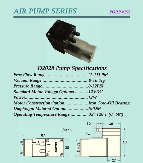
To test a compressed air source, I tried to build a ghetto fabulous compressor by hooking a really cheap 12V tire compressor to an old propane tank that I had converted into an accumulator:
 This worked a bit, but it took about 30 minutes to pressurize the tank to 40 PSI, and after the third time, the poor little compressor blew a gasket.  So much for plan A.

Plan B was to rent a compressor:

I hooked this up with a T into the gas line, with a check valve at the gas line to make sure the air didn't flow back into the gas line.  The compressor went up to 120 PSI, but the regulator on it wouldn't go above 60 PSI.  This turned out to be plenty though, at least for my initial tests.  Simply mixing the gas with the air, even at 20 PSI, would blow out the flame.  The regulator didn't go much below 20 PSI, so I installed a 1/4" needle valve so I could make fine adjustments to the air flow.  I wasn't able to get any improvement over the usual observations: poor flame, mostly confined to the sheath and blowing out the ends.  This was at low gas and low air flow.  At higher air flow, the flame would blow out, and at higher gas and air flow, it was about the same.

If I removed the shuttle from the sheath and ran the gas at 30 PSI, it produced a great flame.  If I slowly introduced air, I could create a nice blue flame, clearly modulating the air/fuel ratio.  By adjusting it this way, out of the sheath, I was able to ensure that I was getting the right ratio.  But putting the shuttle back in situ, the results were very similar to before, little or no sustained flame.  This suggests to me that the primary issue may not be air mixing, but ineffective ventilation of the exhaust: as soon as the gas starts burning, exhaust builds up in the chamber and snuffs the flame.  I would still expect the gas to burn under these conditions if I'm supplying enough air.  But it's possible that the "correct" ratio that I see with the shuttle in the open air is a result of the introduced air + the atmospheric air, and that in a confined space, the lack of the latter is enough to kill it.  This would suggest that it IS possible to supply enough air with the fuel, possibly.

I next tried an air manifold that inserted along the bottom of the chamber.  I took a 1/2" pipe and drilled 1/4" holes at 10" intervals, 10" from each end (so, 6 holes total).  I machined plates that fit over the fan intake fittings to hold it in place.  This also would help force the introduced air up towards the flame outlets at the top, instead of simply flowing out the open ends.


I ran these at 60 PSI, at pretty high flow rates, and fiddled with the gas to get various effects  Here's what I got at about 30 PSI gas:


The flame isn't very tight, but I'm definitely getting a translation.  At higher PSI, instead of getting a larger flame, it was simply getting spread out further, getting less localized.

I have an idea next to simply improve the ventilation of the sheath by cutting the upper half of the sides off, and seeing if this gives me the desired effect; if it does, then I can possibly reintroduce some shielding by adding sections of 6" diameter HVAC conduit.  The purpose of this is to keep the innards hidden, so that the mechanism isn't obvious.  This is the real issue I'm seeing: if I cut the top off the sheath, this would probably work, but then it would be obvious what the mechanism was, and the aesthetic would kind of be ruined.  So trying to get this to work inside the sheath, or SOME kind of sheath, seems like what I'd like to do.  Possibly going to an even larger sheath, or adding more holes to the top, or all of the above could also help with ventilation and exhaust.  Some progress, but still needs work.

Sunday, September 27, 2015

Build details on shuttle prototype v5.1

After the relative success of the shuttle prototype, I've been trying to scale this up into a design that is more similar to what I imagine the eventual final design will be like, which is to say, I've been working on building something that doesn't suck, and that I can use as a blueprint for a final design. I've stopped keeping track, but I think given the gas mixing prototype, rotational valving, translational valving, multiplexing, and shuttle prototypes, this is major version 5, making this Flaming Icosahedron v5.1.  I've done some basic experiments with it, but I wanted to take the time to write up some of my build notes here.

The sheath is made from 6"x3"x5 foot rectangular tube, 0.120 wall, which I got from Bayshore Metals.


I drilled 1/4" holes at 1/2" intervals along the top.  I managed to basically destroy my 1/4" bit along the way.  I actually took it over to the bench grinder and (after watching a YouTube video) re-ground the tip by hand, badly, but well enough to get me through the end of the drilling.  But I bought a $20 bit grinding jig for next time (and also a new 1/4" cobalt tip.)

I've posted photos of the new shuttle build before,in my last post.  I moved the rail holders to the inside to reduce the width.  The rail holders are just cut up pieces of 3/8" black pipe (which is weldable, unlike galvanized pipe.  Welding galvanized metal is a great way to inhale zinc byproducts, which will kill you slowly and painfully.)  
I also made some little clips for holding the 16ga cable in place (in v5.0, I was using picture wire twisted in place, because it's what I had lying around.  None of that bush league crap this time.)

Here you can see the shuttle in place on the rails (1/4" rod from the hardware store), with the gas supply line in place on the shuttle.

The rails are held in place on the ends with 16ga sheet metal that I bent using a handbrake and drilled and tapped holes into the sheath.  I welded 3/8" pipe to the ends, and tapped holes for set screws.
Initially, I hand measured and cut the sheet metal, but for the second set I made, for the fan intakes (below) I ran these on the water jet cutter, and it saved a lot of time.  Those needed a hole in the center for the fan intake, which would have been much harder to do by hand anyway.

Fully assembled (without the fan intakes), you can see the shuttle running along the rail very smoothly, dragging the looped-back gas line with it:

This is another one of those things where, after a week of construction, I was so happy with the results that I sat there playing with it for at least 10 minutes, just pulling the shuttle back and forth, because it worked so smoothly.  It's not a complex machine.  It's just great to imagine a thing, sketch it on the back of a donation insert at high holiday services, and then make it.

I ran a preliminary test without the intake fans, to see how it would work without any additional air, and the results were pretty predictable; at about 30 PSI, I could get okay functioning near the ends, but towards the center the flame snuffs out due to too little air:


  At 50 PSI (closer to where I'd like to run it), it doesn't really work at all.  I attached the intake fans and tried again, and the results were at first better, but there was a flame-out inside the sheath.  I see this pretty often: if not enough air gets into the middle, the fire can go out.  When propane reaches the open end, it flares up and comes out the end in a jet.  This is what you see at the beginning of this demo from v5.0.  There's no video of this run, but in this case, the flame jet came out through the intake (which was providing the air that the fire was seeking), destroying the intake fan:


So, from a build perspective, it's solid, and it works well.  I'm going to disassemble it today to check the hose, and make sure the flame-out didn't damage it.  But getting enough air in is going to require a different design.  Luckily, there are several design I'm considering: adding forced air through a compressor, adding more ventilation to the sheath, and also, carburation.  I found this design online, and reached out to the author:


I have an SMC vacuum ejector that I plan to use as my next test after I check for hose damage.  Progress!


Wednesday, September 16, 2015

Building industrial grade fire art

I was able to make the shuttle prototype functional, at least marginally, by simply slapping a fan on one end to push more air into the chamber.  Here are the results:

There's some wind, and I'm not running the gas at very high volumes, but you can see it clearly translate from one end to the other as I pull the shuttle through.  If you look at the second video closely, you'll also notice that the tygon tube has burned off the end by the time I get it back through: stress + heat = failure.  I'm very happy with this design overall, though, and am now trying to scale it up to fix the problems.  First, I came up with a new, much larger design spec, using a 3" x 6" x 5 foot sheath.  The 6" height should give me enough space to use a low-pressure braided LPG hose, which is much less flexible, and keep it well out of the way of the shuttle.  I've also redesigned the shuttle, which will run along rails

It came out a little too wide, I'm going to have to grind off the tubes which run along the rails (actually 3/8" black pipe) and move them closer to the center.  But the concept is there.

The rail will run along the top half of the 6" height, leaving the bottom half for things like hose clearance (mostly), but also having a fan on either end to push air in, some room for gearing and a motor to move the shuttle back and forth, etc.  I also started machining the ends of the sheath, which will hold the rails in place (and the fans):
These are 16 ga steel sheet which I cut and bent, then tapped holes in the sheath to hold them in place.  Fun stuff.  I screwed up the bending the first couple of times, took some practice to get it right.  But this one fits nicely.

So, this is not a "proof-of-concept" prototype.  This is intended to be an actual model for what I might eventually build to bring to the Playa, and is industrial-grade.  No joke.


Friday, September 11, 2015

Carburetion vs forced air

Some really interesting reading this morning on strategies for mixing air and gas to the right ratio.  Based on last night's experiments, this will be key to getting this to work, and I've seen gas/air mixing as critical to almost every prototype I've worked on.

Basically, you need about 96% air and 4% propane to get a good burn.  In a confined space, like the sheath tube I'm using, getting enough air in there requires an active strategy.  One strategy is to just pump air into the sheath.  This is the simplest thing, and probably what I'll try first: drill some holes in the side of the sheath, and hook up an air pump.  It's inexact, but it should work.  If I go to a pressurized air tank, I can get higher flows, and use a needle valve to tune the ratio.

But an interesting alternative is to build a carburetor that pre-mixes the propane and air.  A carburetor basically uses the Venturi effect to draw air into the stream actively before the gas reaches the outlet.  This is a good example of such a design, for a propane burner that can burn much hotter than just burning raw propane:

The writing is unfortunately pretty bad, but the gist is that the teeny hole in the middle pipe lets out propane, and it draws air in through the giant hole in the reducer.  There's not much in the way of tuning, but it works pretty well apparently, possibly just based on the specific hole sizes used.  Using a design like this in the shuttle would be complicated; it's not clear how I would adapt this.  But it's a starting point for some thinking on how to make this work.

Thursday, September 10, 2015

Quick update on the shuttle prototype

Got back from the burn and have been working on the shuttle prototype; had some good time to think about it while I was at TTITD.  Here's was the first version of the shuttle:

It used a pair of circular brackets, made from pieces from previous prototypes (I always get a bit teary-eyed when I cut up an old prototype to make a new one, but the cycle goes round-and-round.)  This was elegant, but it tended to rotate while passing through the sheath, so I had to scrap it.  The current version looks like this:


It's strapped to a couple of pieces of shelf bracket, and I've laid an aluminum rail down on the bottom of the sheath (not shown.)  I didn't film my first experiment, but the result was interesting: it worked well, once.  But it's unreliable because of poor circulation of air to the interior of the sheath.  This is an issue I've seen a lot.  I'm starting to think it might be a major issue with a number of my prototypes.  I can either pump air in (I bought a Shraeder-to1/4" NPT adapter so I can use a car tire as a compressed air source) or open up the sheath a bit.  Haven't exactly decided which.  But a quick test with just using a fan to blow air into the sheath improved it a lot.  Unfortunately the viton came out of the compression fitting after that.  Making sure the compression fitting is secure will be tricky.  In the original shuttle design above, I used a barbed hose fitting with some copper tubing soldered on to make it fit right, and ziptied it in place.  While I think this is actually more secure than the compression fitting, it's not as "legal" according to BMOrg rules.  Getting this approved will require working with them on the design, but for the prototype either is fine.

Saturday, August 29, 2015

Rotary mechanical prototype v3ish: FAILZ0R

My last rotational valving prototype showed some promise, so I decided to try a modification, with a third sheath that had a linear set of openings, so that there would be three layers:

These fit together Russian-nesting-doll style.  There's about a 1" gap between the inner and the middle, so the flame will stay alight, and the inner and outer have only about 1/16" between them, to act as the gate.  I also spent some time making a nice bracket for holding the inner pipe in place without requiring bolts, so that the outer pipe could be flush with the inner pipe.  It slides inside the middle pipe and was welded in place.  Required me to resurrect some sheet metal working skills.


The results of the test were, well, not good:

You do again see some modulation of the flame, but it's a small effect.  My impression is that the double-gating is making it such that no air is reaching the actual gas outlet at the inner tube, and we're only getting ignition as the gas escapes into the "atmosphere."  One problem with building smaller-scale prototypes and scaling them up is that you see these kinds of problems: air flow and gas flow is much worse.  I considered running an air line into the inner tube, and pumping air into it.  That said, I'm not certain that this design is a good idea overall, and I'm going to take a break from it.  The machining is fun, but it's not proving very useful.

I have some work to do on trying to improve the multiplexing prototype, but I'm less bullish on that at the moment as well given the problems.  I've been avoiding this for a while, but I think a much simpler concept might give me a much better aesthetic impression, which is basically just a small pipe that mechanically runs back and forth inside a larger pipe, like a shuttle, carrying a tube along with it, and simply carrying the flame, physically, that way:

I want to use Viton tubing to carry the gas to the shuttle, it's good to 400F, and it's resistant to propane.  But fire art safety might disagree; they seem pretty set on the idea that you can only use manufactured LP hose.  I don't think it's impossible, with a 4" diameter tube, to use manufactured hose.  It might be a future discussion if this design turns out to be good.  Having spent a lot of time working on this, I'm feeling more confident in my thoughts about safety and maybe straying outside the bounds of what is specifically published.  Including something like an excess flow check valve might help, though it might also be prohibitively expensive.

Leaving for the burn on Monday.  No more fire art for this week probably, except for running around with my backpack on.  Come find me at Playasos at 8:45 and B if you're there, and say hi.

Thursday, August 20, 2015

Experiments with flame colorants

I don't think I'll have it ready in time for the burn, but I wanted to try working with flame colorants for The Widowmaker.  Here are some experiments with solid and liquid copper sulfate. I did some experiments with boric acid as well, but those didn't turn out as well.  The key I discovered was to make a saturated solution, then use a very shallow vessle to hold it with a very small hole in the bottom; in this case, I just inverted a 1/2" end cap which had a 1/16" hole in it on top of a pipe, and held it in place with rescue tape.
The results were nice, but the gas blew most of it out.  Spraying it directly into the flame might be workable, but the timing would have to be just right, and I wonder if I can get enough volume.  I don't have a spray bottle sitting around that I want to ruin with copper sulfate just now, so it will wait a bit until I get one from The Jerk Store.

Wednesday, August 19, 2015

Multiplexing scale prototype

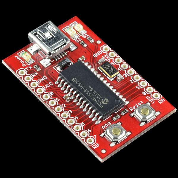
Built a larger scale prototype of the multiplexing concept.  For control, I tried something new, using the USB Bit Whacker:
Instead of using a microcontroller, you can bit twiddle this in Java (or in Groovy, in my case) using simple serial port commands.    I used JSSC for the serial port communication because javax.comm is way too complicated, and as far as I can tell is not part of the JDK or hosted on Maven Central.  (If it's not on Maven Central, I don't need it.)  The main reason for trying the Bit Whacker was that, when using the Arduino, the compile-upload-run cycle is long, and getting feedback (button presses, whatever) into the system is non-trivial.  The Bit Whacker lets me iterate on variables and protocols much more quickly.  Also, I can do things like start it up, open a valve, put it in an idle state waiting for keyboard input while I light the flame, and then hit a button to continue the program.  I can do this really easily, whereas with the Arduino it requires actually attaching a button and reading input from it.

I placed 6" lengths of 1/16 inch holes at six inch spacings, with 3 strands with 3" overlaps.  I re-used the valve array plumbing from the electromechanical prototype.  Here are some test videos at two different flow rates:


The lighting makes it hard to see what's going on, but there are two main problems:  First, because there are holes all along the length, the gas pressure at the distal end is much lower than at the proximal end.  This is especially apparent in the first video.  This is easily fixable by creating a loop of the tube and plugging both ends into a t-junction, but it's more plumbing, and a pain in the ass.

Second, in the second video, you can see that the first segment ignites, then the second segment, in sequence, and the first goes out (mostly.)  Then the second ignites the third.  At this point, the first segment comes on again, and should ignite the next length of the first segment.  The problem is that the original position flares back up, and we get two flame fronts.  Why?  Because the flame never actually goes out; when I shut down the gas flow to the first segment, there's still residual propane in the pipe, and it doesn't burn off or go out immediately.  It just goes to a very low flame.  This can persist for minutes at a time.  If I want to continue with this prototype, I'll need to figure out a way to deal with this.  It's not a failure, but there are bugs to be worked out.  Every bug fix introduces new complexity, and the goal is to make the design as simple as possible, but no simpler.

Also notable about this run was that it was the first time I had to use my fire extinguisher.  The solenoid valves are poor quality (I guess that's what you get from $9 a valve on Alibaba) and there was some leakage from one of the unused valves that's supposed to remain closed when unenergized.  I was trying to work around it so I could do a quick and dirty test, but it caught fire, and wouldn't go out because of the volume of gas leaking.  I decided to extinguish it for safety, since it was close to a few things that I didn't want to catch on fire.  Safety third!  (A friend of mine told me once that they saw a t-shirt that said:

1) Porn
2) Bacon
3) Safety

But I can't find it on the intarwebz.  Would be fun to have.  Suppose I could make one.)

Sunday, August 16, 2015

Successful test of the fire poofer backpack

Bad video quality, but it worked.  I'm probably going to replace the PVC with copper, since the top did stay on fire a bit after the initial poof, and it did char the top of the PVC.  But otherwise, total success.

I'm thinking this thing needs a name, I'm thinking of just calling it The Widowmaker.  But I'm open to suggestions.